TL494Flyback
Problem Statement
I need high voltage for the HSL SEM electron gun. I want to use a flyback transformer from an old TV so I need a switching topology. I also need it in a way that is adjustable on the fly and won't take up a lot of room. 555 circuits are a pain to calibrate and are not easily adjustable for both duty cycle as well as frequency. At some point it would be nice to have it voltage regulated to a preset voltage level using a high voltage resistor divider feedback network.
System Overview
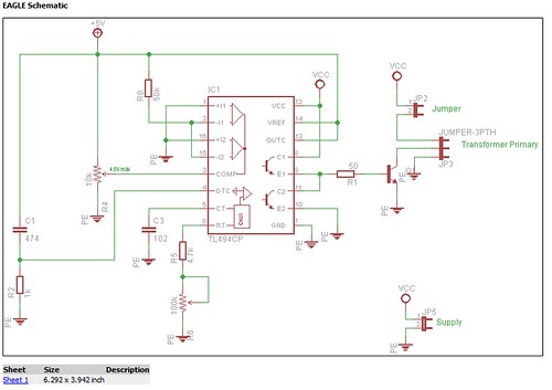
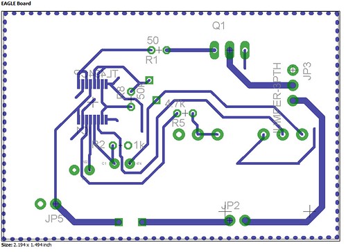
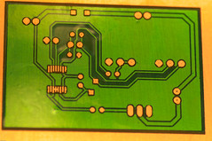
The TL494 is a neat little chip that has just about everything and more that you could need to build a custom switchmode power supply. The only drawback is that it doesn't support duty cycles over 50%. The circuit was layed out in Eagle PCB. Current regulation is not implemented. Note that JP3 also contains a third pin connected to ground so that the bottom of the transformer secondary can be grounded.
PCB
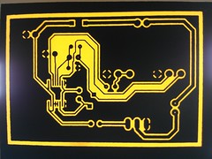
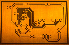
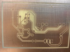
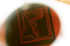
A PCB was etched at Heatsync Labs on their CO2 laser. Flat black spraypaint was used to coat the PCB and then it was ablated in two passes at 35 watts each at 200mm/sec raster rate. Then it was etched in FeCl and a layer of laser etched PET tape was placed over it as a test solder mask.
Results
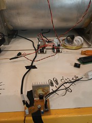
The board works perfectly when powered with a 12V 2A max switching supply and a current limiting resistor inline with the flyback. The limits are imposed to keep the voltage at the flyback to 12kV or lower to prevent X-rays and to control EMI and thermal problems. It would be interesting to use this design with a larger heatsink, better transistor, and a car battery and see if it could be used to power the HiSpeedFlash
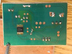
PET tape degrades at 250°C so care should be taken with a soldering operation. I had wonderful results and love the professional look of the totally DIY board. Unfortunately the board had to be hot-air reworked and the PET tape degraded slightly around the components. The boards will look the best if there is no rework operations that need to be performed.
The board is current being used to power the electron gun of the cold cathode beamline on the HSL SEM.
