SEM Lens Drivers
Problem Statement
I need a way to test and control various magnetic optics for the HSL SEM beamline. I want to design these are linear current sinks, so that switching noise won't be a problem during high speed rasterization. I want them to be capable of manual control but also digital override at some point.
V1U
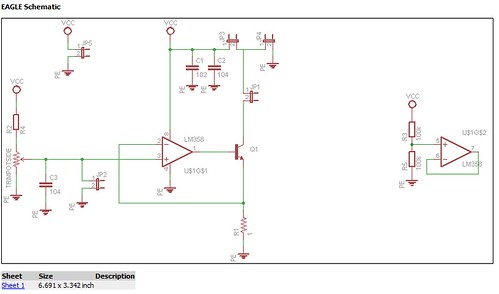
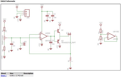
The first version uses a single rail-to-rail op-amp to set the voltage across (and due to Ohm's law, the current through) a sense resistor. The second op-amp in the package is connected unused. The sense resistor must be large enough to generate a large enough signal to reference against. This is a weakness because using a large sense resistor also dissipates more power. The design will only work with focusing lenses as it is unipolar and can only push current in a single direction.
Jumpers are available for digital feedback and control of the lens current as well as a separate (if required) driving vs logic voltage. Future versions should have a small footprint to include an optional onboard voltage regulator.
V1.1U
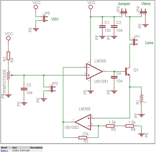
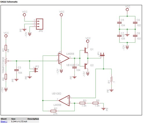
An upgraded design that uses the second op-amp as an error amplifier to boost the sense resistor voltage. This means much smaller resistors can be used, which dissipate less power. The design also uses more decoupling capacitors to deal with the fact that noise is also amplified.
V1B
This is a bipolar version of the V1U unipolar design. It uses a complementary pair and requires a bipolar power supply for operation. It will also require a bipolar control voltage, which is a major weakness as any digital integration will need to translate the control voltage to be bipolar.
V1.1B
This is a bipolar version of the V1.1U unipolar design which uses the second op-amp as an error amplifier.
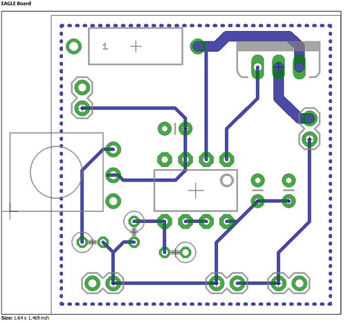
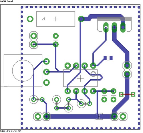
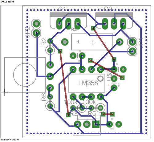
PCB
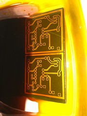
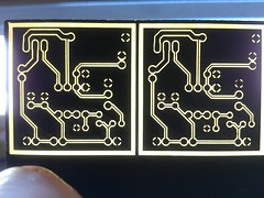
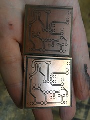
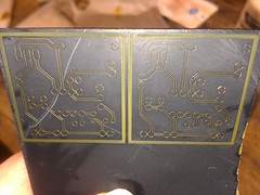
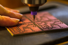
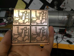
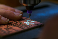
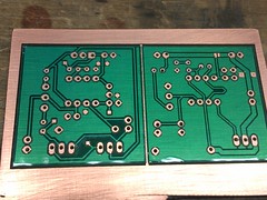
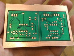
A PCB was etched at Heatsync Labs on the CO2 laser. Flat black spraypaint was used to coat the PCB and then it was ablated in two passes at 35 watts each at 200mm/sec raster rate. Then it was etched in FeCl and a layer of laser etched PET tape was placed over it as a test solder mask.
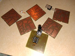
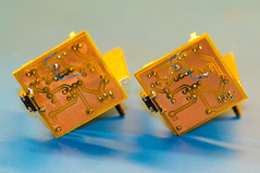
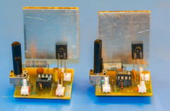
Results
The current sinks work as expected. The bipolar designs have not been validated. As a bonus, these make great high current LED / Laser Diode drivers as well.