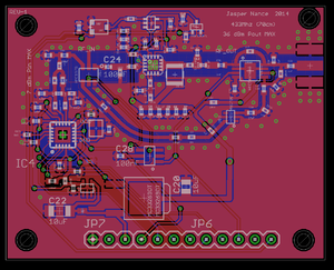
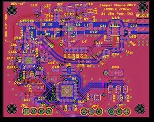
CC1101 Bidirectional PA Module
Problem Statement
My Metalocalypse / Klingon inspired quadcopter needs a communications system capable of command and control data uplink and telemetry data downlink. I would prefer to have these on the same RF link. On the drone side, this is because space for radios, power, and antennas is very limited. On the ground side, I want to be able to travel with this system and not have to do a ton of setup to fly. I really need to be able to just whip out a remote and fly this around with or without a PC or all sorts of antennas and hassle.
I want the link to be one of the most robust systems. I want to be able to outfly my FPV system so that I can always be sure that if I can see it, I can command it, and I can command it back home even if blind. I chose 433Mhz because it has a longer range than higher frequency alternatives but still has manageable antenna sizes. Note that to use this frequency and power level you will need a HAM radio license.
Design
A PC Board is ready for fabrication which contains a CC1101 chip, a low power RF Switch, a 4W PA, 11dB LNA, and a 10 Watt T/R switch. The ground side will interface through SPI to my DIY RC controller board via 100 mil header. The flight side will contain an onboard MSP430 for RS232 translation of data packets to the flight computer and radio management tasks. The entire board is designed to run at 3.3V and contains onboard regulators to interface with a 5V BEC output from one of the speed controllers.
Transceiver
The CC1101 is a chip from TI that I use on a lot of my RF projects. It can output 10mW at 433 or 915Mhz. I have implemented a custom matching network that should work for both bands, making this board quite flexable.
RF Switches
The HMC197B is a DC-3Ghz RF switch. It is used to steer the CC1101 RF path from the LNA output to the PA input. Both inputs are N/O so in order to command A and B with a single signal, a 74HCT2G04 chip (2 gate SMD version of the 7404 hex inverter) can be used to produce the proper logic inputs.
The HMC546MS8G is a 0.2-2.2Ghz T/R switch that can handle 20 watts. It is used to steer the antenna to the PA output or the LNA input.
PA
The PA I used is a GSM centric amplifier, the RF5110G which can output up to 36dBm. I have successfully used this chip in the past as a Big Red Bee amplifier and I was able output 4W into a 1/4 wave magnetic base antenna. It will also work at 915Mhz if the matching networks are appropriately modified.
LNA
The LNA is an HMC374 0.3-3Ghz amplifier with 11dB of gain.
Micro-controller
The µProc is an MSP430F2274 16-bit, 16Mhz processor with a SPI interface to the CC1101 and a 3.3V TTL interface to the flight controller. Three LED indicators are available as well as an ADC channel to read in the voltage of the supply given on the Vbatt pin (either 5V or 1S only!).
Development Chronology
June 11th, 2014 Design started.
June 13th, 2014 Ground side design complete
2014 Jasper Nance KE7PHI

