File:Linear Dimmer CAT4101.png
From NebarnixWiki
Jump to navigationJump to search
Size of this preview: 799 × 278 pixels. Other resolutions: 320 × 111 pixels | 1,184 × 412 pixels.
Original file (1,184 × 412 pixels, file size: 19 KB, MIME type: image/png)
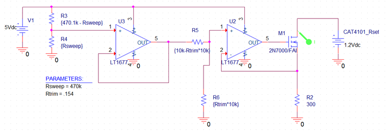
Brightness control is achieved by dividing a 0-5V signal generated by the brightness trimpot then using the resulting voltage to set a current through a sense resistor. The sense resistor is 300Ω, meaning that the voltage across it for 2.5mA is 750mV. Thus, the divider must then be set to divide the buffered 5V signal by 6.67, or 15% of a trimpot. The circuit uses both sides of a dual rail-to-rail op-amp.
File history
Click on a date/time to view the file as it appeared at that time.
| Date/Time | Thumbnail | Dimensions | User | Comment | |
|---|---|---|---|---|---|
| current | 11:48, 26 February 2014 | 1,184 × 412 (19 KB) | NebarnixWikiSysop (talk | contribs) | Brightness control is achieved by dividing a 0-5V signal generated by the brightness trimpot then using the resulting voltage to set a current through a sense resistor. The sense resistor is 300Ω, meaning that the voltage across it for 2.5mA is 750mV. Th |
You cannot overwrite this file.
File usage
The following page uses this file: