TeslaCoil
Problem statement
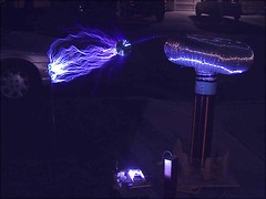
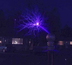
There is not enough lightning at my disposal.
Device Description
A classic Tesla Coil, consisting of a tank circuit fed by a relaxation oscillator which rings in response to a capacitor discharge over a spark gap fed by 60Hz AC at 12,000 Volts.
Transformer Protection
Neon sign transformers are current limited by magnetic shunts in the core. This means that the outputs can be safely shorted to each other or ground without worrying about damaging the transformer. However, driving capacitive loads will cause cancelation of these inductive looking magnteic shunts and an overcurrent condition can destroy the transformer. Also, RF energy and transient voltage spikes as well as capacitive induced oscillations can contribute to the failure of the high voltage insulation within the transformer, sometimes within seconds (as could be the case when directly driving the tank capacitor if the spark gap fails to discharge).
In order to protect the transformer from these dangers, a series of protective devices were constructed. Two RF chokes in series with the tank circuit block the tank circuit RF from getting back into the transformer. This should also attenuate any transients caused by the tesla coil secondary output being reintroduced into the primary. The next line of defense are two beer bottle capacitors which will shunt any high frequency transients that make it past the RF chokes to ground instead of into the transformer. The last line of defense is a spark gap which will fire if any voltage on the transformer output is larger than the rated voltage. The spark gap is tuned to fire between one to several times a second in response to any kickback from the tank circuit that makes it past the chokes and the beer bottle caps. Note that the beer bottle caps and the emergency spark gap can create an unwanted tank circuit if the gap is too small (setting up a relaxation oscillator directly at the transformer output)
Results
The coil has been through multiple design phases.
Version 1
Around 1999. Mostly lost in the winds of time as I was 16 and didn't own a camera or have any money. It was run off of a DC flyback which resulted in a pulsed mode operation as well as a 9KV 30mA neon sign transformer which I ended up breaking (lack of protection circuitry) and a 15KV 30mA transformer which I stupidly connected directly to a large capacitor for fun. I also broke another 12KV 60mA transformer which failed after months of operation during a spark gap failure. The capacitors in version 1 were stacked glass caps submerged in veggie oil. It was disgusting. Don't ever do that. Ever. It is not worth putting your arms in oil up to your elbows and destacking every time a little water or bacteria or dead ants or a single point failure causes a glass plate to crack.
Version 2
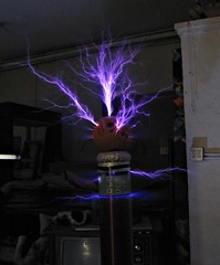
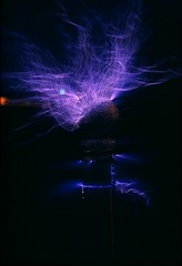
Version two will be shown below and is a snapshot from around March 2004 just before I scrapped the setup and started over. The setup was difficult to move and had problems with structural integrity often times requiring repairs caused by arcs forming between the spaghetti like wires. This is no way to treat high voltage!
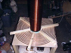
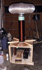
Version 3
Version three was an effort to do things the right way and make the design portable without spending endless time on setup and takedown. It was on wheels. MOBILE MEGAVOLT EXPRESS! It is currently sitting in a storage shed in North Idaho but suffered some mildew problems which caused the wooden structure to become conductive and carbonize. Whoops.

Version 4
Version four is currently in work over at heatsync labs as a collaborative effort to be ready by Oct 23, 2010