Difference between revisions of "FieldStops"
| Line 10: | Line 10: | ||
OpenSCAD is a dream. I wrote the following script which even includes kerf compensation. It auto generates and even neatly tiles the two pattern sets. Then I can export right to DXF. This is my first openSCAD project. I think I am hooked... | OpenSCAD is a dream. I wrote the following script which even includes kerf compensation. It auto generates and even neatly tiles the two pattern sets. Then I can export right to DXF. This is my first openSCAD project. I think I am hooked... | ||
| − | ==Results== | + | ==Script Results== |
| − | + | There is a kerf bug. Technically the kerf is the entire width of a cut, not the difference between expected and actual edge coordinates. The script is actually looking for 1/2 of the kerf. So if your cut is 0.3mm wide then you need to put in 0.15mm as your kerf. Oops. I'll fix that someday. | |
Here is the openSCAD script. [http://svn.nebarnix.com/sub/CAD/laser/microscope_stops.scad] | Here is the openSCAD script. [http://svn.nebarnix.com/sub/CAD/laser/microscope_stops.scad] | ||
| Line 22: | Line 22: | ||
And here is a pdf file you can use to laser your own set but really you should just load the openSCAD script and customize it yourself! CMON LAZY BONES! [[Microscope_stops_0kerf15mm.pdf]] | And here is a pdf file you can use to laser your own set but really you should just load the openSCAD script and customize it yourself! CMON LAZY BONES! [[Microscope_stops_0kerf15mm.pdf]] | ||
| + | |||
| + | ==Laser Results== | ||
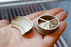
| + | Using 1mm thick cardstock at a power of 20 Watts and a travel speed of 10mm/sec I was able to produce the following. I assumed the same 0.15mm halfkerf. The results are amazing! The spars and ring are thick and sturdy and they fit perfectly in my filter tray! | ||
| + | |||
| + | <flickr>8555579059|thumb|none|m|All Stacked Up.</flickr> | ||
Revision as of 14:05, 15 March 2013
Problem Statement
I want darkfield and oblique stops with my low and medium magnification objective lenses on my compound microscope. I want them to be repeatable in case they break or I find another needy scope. I want them easy to make and use so I can share them with the world. They need to fit in the filter tray. I also don't really know what sizes I need so I want a way to generate a laser cuttable geometry that can sweep a variable over whatever range.
Solidworks
First I made a few patterns in solidworks but I wanted to be able to change things like arm spar geometry and swept range really fast and painlessly. That is not solidworks. I wanted to change one thing and have it carry through the entire swept set. And kerf compensation because the laser at HSL doesn't automatically apply it. Yikes... Onward towards a better solution...
OpenSCAD
OpenSCAD is a dream. I wrote the following script which even includes kerf compensation. It auto generates and even neatly tiles the two pattern sets. Then I can export right to DXF. This is my first openSCAD project. I think I am hooked...
Script Results
There is a kerf bug. Technically the kerf is the entire width of a cut, not the difference between expected and actual edge coordinates. The script is actually looking for 1/2 of the kerf. So if your cut is 0.3mm wide then you need to put in 0.15mm as your kerf. Oops. I'll fix that someday.
Here is the openSCAD script. [1]
And here is what it spits out (DXF) [2]
And here is a render of what it spits out (PNG) 
And here is a CorelDraw render of the DXF 
And here is a pdf file you can use to laser your own set but really you should just load the openSCAD script and customize it yourself! CMON LAZY BONES! Microscope_stops_0kerf15mm.pdf
Laser Results
Using 1mm thick cardstock at a power of 20 Watts and a travel speed of 10mm/sec I was able to produce the following. I assumed the same 0.15mm halfkerf. The results are amazing! The spars and ring are thick and sturdy and they fit perfectly in my filter tray!