CC1101 CC2500 Bridge
Problem Statement
The new CC430 chips contain a 70cm/33cm radio which has an output power is 10mW; these are used in the EZ430-chronos wristwatch. My camera remotes and Toyota Yaris both use the same radio in the form of a CC1100. The EZ430 boards use a similar radio in the 12cm band at 3.3mW. Since I would like to use combinations of both systems, it makes sense to bridge the two networks. This could be done at the PC end by using two USB receivers, but that really isn't optimal since the PC is usually in a bad signal area and the repeating would be done in PC software so speed would be limited. A repeater or data bridge could be placed in a central and signal-strong location (in the attic even) with large (1/4 or 1/2 wavelength) antennas. This would automatically cross band repeat both networks.
PC Board
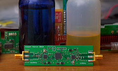
A PC Board has being fabricated which contains a single MSP430F2471 chip and two radios - a CC1101 and a CC2500 radio. No LNA's or amplifiers are present though I seriously considered adding them and might still as an addon or as a new board revision.
Development Chronology
July 16th, 2010. Boards arrived, need to order parts to populate.
Sept 25h, 2010. Parts arrived and board populated! Software needs written.
Sept 27th, 2010. Software is written but there are problems. The CC1101 chip won't boot and the CC2500 chip says its transmitting but I don't pick up anything using an RF2500 receiver. Hopefully its a software problem and not a solder-paste problem (shorting pins under the packages?)
Sept 29th, 2010. Found some delicious bugs in both radios, mostly linked to overlapping peripherals resulting from re-using old code. Problems found, problems solved! The last remaining problem is the choose a protocol for the CC1101 and stick to it IE re-code all of the other boards I have including the CC430 wrist watch to match or perhaps choose a backup and program the board to switch to a (for example) higher birate mode.
Oct 2th, 2010. Discovered that 2.5V Vcc is not enough for stable operation at 16MHz nor 12MHz. Damn. All sorts of weird lockup problems were resolved by clocking the MSP430 at 8MHz. Fixed a minor bug regarding fixed-length packet mode.
Jan 22nd, 2013. Intermittant failure of the 2.5ghz radio, cracked solder joint or software error with the new MSPGCC release? hmm!
Source Code
Can be found here (For reference only, all rights reserved)
Results
The finished board fits inside of an altoids chewing gum tin (long and skinny) and allows the antennas to protrude from the sides. The board draws 40mA steady state when set to maximum sensitivity mode. An 800mAH ipod battery fits nicely inside of the case and will last approximately 20 hours on a full charge.
2010 Jasper Nance KE7PHI