Difference between revisions of "3D printed LED Ringflash"
m |
m (Added pic of 3D printed hotshoe mount) |
||
| Line 53: | Line 53: | ||
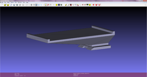
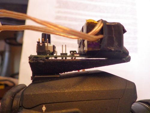
The hotshoe mount has been designed but not printed yet. Standby for further revisions. | The hotshoe mount has been designed but not printed yet. Standby for further revisions. | ||
| − | [[Image:RingflashHotshoeMount.png|500px]] | + | [[Image:RingflashHotshoeMount.png|left|500px]][[Image:RingflashHotshoePCBholderAssembled.jpg|none|500px]] |
Revision as of 12:10, 31 March 2014
Problem Statement
Macro subjects are hard to capture with even lighting. It is easy to shadow the subject due to the close proximity of the lens. The solution is to use a ringflash. They are expensive and I thought it would be fun to design one myself. I wanted to create two different units, one with LED lighting and one with actual flash tubes. I don't want to use digital control. This is both a personal challenge and a robustness requirement. If it "Just Works" (TM) I'll be more likely to use it than if it needs software written and tweaked and uploaded and interfaced with blah. I also want it to be very small so that it can be mounted on the hotshoe. I want something that will have power saving measures if I want to go traveling with it.
System Overview
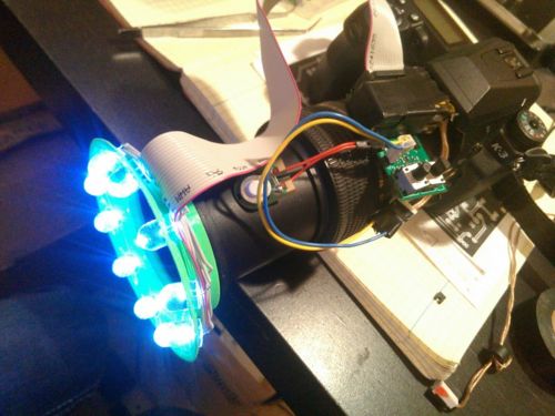
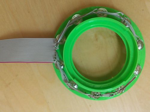
The system consists of a controller PCB, a 3D printed mount for the controller PCB, a power source, a 3D printed structure to mount the lights on, and the lights themselves.
Controller
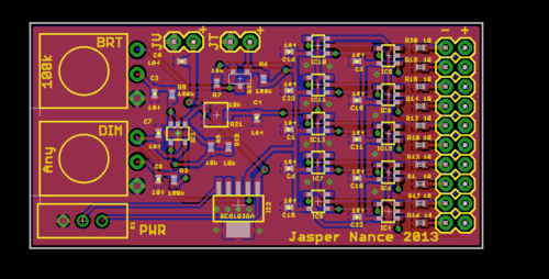
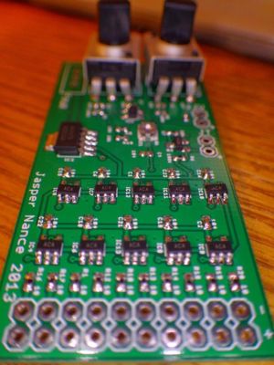
The controller uses a 5V 500mA REG103GA voltage regulator. I chose 10 LED channels because when I hooked up 5x NTE30071 it wasn't bright enough. More than 10 seems silly and like I should be doing something else with the space, like buck-boosting to a level where the LEDs could be in series. This means that each channel can output up to 50mA.
There are two dials, one sets the "focus" brightness which is always on, and the other sets the "flash" brightness, which is meant to be used for the actual photo.
BOM Notes
Reg to use: http://www.ti.com/product/reg103-5 (SOT223-5 package)
Op-amps to use: MCP6L71/1R/2/4 http://ww1.microchip.com/downloads/en/DeviceDoc/22145a.pdf
LEDs to use: NTE30071 http://www.radioshack.com/product/index.jsp?productId=12580024
Trimpot to use for setting reference voltage TC33X-2-103E http://www.digikey.com/product-detail/en/TC33X-2-103E/TC33X-103ECT-ND/612911
Simulation
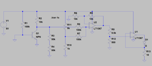
The circuit was simulated in LTSpice and checks out.
LEDs
At first I chose NTE30071 LEDs. This seemed like a great solution because they're bright, they run at 25mA, and they have built in 40 degree lenses, so at least for closeup work they should be bright. However, in practice it was found that the light was not even (it was shaped like a halo), the LEDs were not bright enough, and the color temperature varied significantly between LEDs.
For V2 I have ordered some Cree CLA1B-WKW series LEDs which are much brighter (10 lumins instead of 3 at 30mA), have even 120 degree light, and can be run at up to 80mA.
Structure
Ring
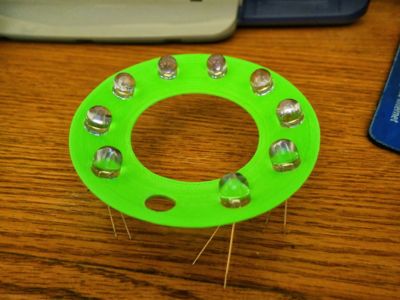
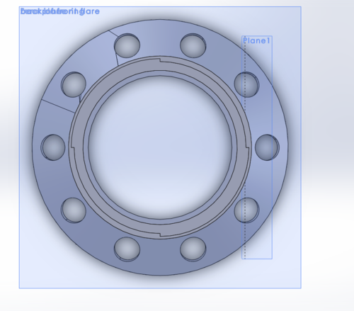
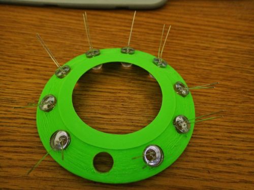
The ring structure was designed to be very basic, it is just a cone that aims the LEDs towards the closest focus spot on my 90mm tamron macro lens. It took about three revisions to find a design that printed well and was robust enough to stand up to testing.
Mount
The hotshoe mount has been designed but not printed yet. Standby for further revisions.
