Difference between revisions of "Img2gco"
| Line 5: | Line 5: | ||
The script can be acessed at the following link: http://www.nebarnix.com/img2gco/ | The script can be acessed at the following link: http://www.nebarnix.com/img2gco/ | ||
Jpeg, gif or PNG images can be used and they do not require conversion to grayscale (that happens inside with the magic and stuff). I am not quite sure what happens if you feed it grayscale images. Also, depending on your machine's axes the image may or may not need flipped or rotated. At some point I will implement this but for now you should make a small 10mm test and see for yourself. | Jpeg, gif or PNG images can be used and they do not require conversion to grayscale (that happens inside with the magic and stuff). I am not quite sure what happens if you feed it grayscale images. Also, depending on your machine's axes the image may or may not need flipped or rotated. At some point I will implement this but for now you should make a small 10mm test and see for yourself. | ||
| + | |||
| + | ==How To Use== | ||
| + | Notes: | ||
| + | #Results are amazing but speeds are SLOW because 3D printers weren't designed as laser engravers or something?! | ||
| + | #The output g-code will contain some information in a commented header section, and one of the pieces of info is the commands per second. This is very important. My Printrboard can handle about 280 commands per second over USB and about 380 when printing from the SDcard. This is somewhat abstracted to this program only because commands can vary considerably in length, but if you exceed the capability of your firmware the motion will stutter and your image will look like crap. If this happens, either lower the horizontal resolution or slow down the scan rate. | ||
| + | #This script uses a simple color=>grayscale conversion. If you want to map the brightness differently, please do this in the photo editor of your choice. (TODO: add grayscale preview so you can see what the various colors will look like) | ||
| + | |||
| + | |||
| + | At the website you'll see the following: | ||
| + | |||
| + | * '''Laser Min Power''' [0-255]: - This is the laser power that corresponds to WHITE | ||
| + | |||
| + | * '''Laser Max Power''' [0-255]: - This is the laser power that corresponds to BLACK | ||
| + | |||
| + | * '''Laser 'Off' Power''' [0-255]: - This is the laser power that will not mark the wood at all, even if it just sits there. Usually this is the bare minimum that your PWM board will respond to. | ||
| + | |||
| + | * '''Skip over values above''' [0-255]: This defines the white level. In a JPEG the white level probably contains some compression artifacts so you might have to go down to 252 or so. PNG images should have white at 255 so 254 is a good value. (TODO: preview the image with this level hi-lighted) | ||
| + | |||
| + | * '''Travel (noncutting) Rate''' [mm/min]:" - Slewing between places speed. | ||
| + | |||
| + | * '''Scan (cutting) Rate''' [mm/min]: - Speed to move while lasering. This is usually limited by the commands per second rate of your firmware, you can go faster from an SDcard than over USB. You will need to find this speed, and note that the power levels will need tweaked if this speed is changed. | ||
| + | |||
| + | * '''Overscan Distance''' (prevents twang from showing) [mm]: - This sets a 'blank' distance before the start of the line to give the belts time to settle down and the motors to reach constant speed. | ||
| + | |||
| + | * '''Height''' (width autocalculated) [mm]: - set the height, the script will autosize the width. (TODO: add an either/or option) | ||
| + | |||
| + | * '''Horizontal Resolution''' [mm/pixel]: - mm between pixels. If you make this larger you can attain faster speeds, but at the price of some detail loss. 0.1 is really amazing 0.15 is nearly so. 0.2 starts to look a little fuzzy. Beyond that you will probably see pixelization. | ||
| + | |||
| + | * '''Scangap''' [mm/line]: - This is the distance between lines which is a function of your laser spot size. You need to make this small enough so there aren't visible unburned lines. For my laser this is 0.05 though I can usually get away with 0.075 because its faster. 0.1 leaves visible lines, which is kind of a cool effect. You can try to defocus your laser to make thicker lines for shorter overall total time, but you will have to increase your power. Note that if lines start to overlap you might need to bring your power down slightly. | ||
| + | |||
| + | * '''Start X''' [mm from 0 for right of image]: - X value to start image from. The laser will start here and move in the positive direction as it scans. | ||
| + | |||
| + | * '''Start Y''' [mm from 0 for top of image]: - Y value to start image from. The laser will start here and move in the positive direction as it scans. | ||
| + | |||
==TODO== | ==TODO== | ||
Lots of stuff to do, but it would be nice to have: | Lots of stuff to do, but it would be nice to have: | ||
| + | * Define start X,Y to be in various spots (lower left, lower right, center, upper center, etc) | ||
* Bidirectional mode | * Bidirectional mode | ||
* Flip images with tic boxes (in case machines have inverted coordinate axes -- 0,0 NOT front left) | * Flip images with tic boxes (in case machines have inverted coordinate axes -- 0,0 NOT front left) | ||
Revision as of 09:47, 14 April 2015
Problem Statement
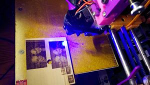
I got a 2W blue laser and I zip tied it to my 3D printer to cut simple shapes out of paper and cardstock. I attempted to find rasterization programs for image etching but I could not find anything worth using. I decided to write my own program because it seemed somewhat trivial yet also, well, lasers!
Link
The script can be acessed at the following link: http://www.nebarnix.com/img2gco/ Jpeg, gif or PNG images can be used and they do not require conversion to grayscale (that happens inside with the magic and stuff). I am not quite sure what happens if you feed it grayscale images. Also, depending on your machine's axes the image may or may not need flipped or rotated. At some point I will implement this but for now you should make a small 10mm test and see for yourself.
How To Use
Notes:
- Results are amazing but speeds are SLOW because 3D printers weren't designed as laser engravers or something?!
- The output g-code will contain some information in a commented header section, and one of the pieces of info is the commands per second. This is very important. My Printrboard can handle about 280 commands per second over USB and about 380 when printing from the SDcard. This is somewhat abstracted to this program only because commands can vary considerably in length, but if you exceed the capability of your firmware the motion will stutter and your image will look like crap. If this happens, either lower the horizontal resolution or slow down the scan rate.
- This script uses a simple color=>grayscale conversion. If you want to map the brightness differently, please do this in the photo editor of your choice. (TODO: add grayscale preview so you can see what the various colors will look like)
At the website you'll see the following:
- Laser Min Power [0-255]: - This is the laser power that corresponds to WHITE
- Laser Max Power [0-255]: - This is the laser power that corresponds to BLACK
- Laser 'Off' Power [0-255]: - This is the laser power that will not mark the wood at all, even if it just sits there. Usually this is the bare minimum that your PWM board will respond to.
- Skip over values above [0-255]: This defines the white level. In a JPEG the white level probably contains some compression artifacts so you might have to go down to 252 or so. PNG images should have white at 255 so 254 is a good value. (TODO: preview the image with this level hi-lighted)
- Travel (noncutting) Rate [mm/min]:" - Slewing between places speed.
- Scan (cutting) Rate [mm/min]: - Speed to move while lasering. This is usually limited by the commands per second rate of your firmware, you can go faster from an SDcard than over USB. You will need to find this speed, and note that the power levels will need tweaked if this speed is changed.
- Overscan Distance (prevents twang from showing) [mm]: - This sets a 'blank' distance before the start of the line to give the belts time to settle down and the motors to reach constant speed.
- Height (width autocalculated) [mm]: - set the height, the script will autosize the width. (TODO: add an either/or option)
- Horizontal Resolution [mm/pixel]: - mm between pixels. If you make this larger you can attain faster speeds, but at the price of some detail loss. 0.1 is really amazing 0.15 is nearly so. 0.2 starts to look a little fuzzy. Beyond that you will probably see pixelization.
- Scangap [mm/line]: - This is the distance between lines which is a function of your laser spot size. You need to make this small enough so there aren't visible unburned lines. For my laser this is 0.05 though I can usually get away with 0.075 because its faster. 0.1 leaves visible lines, which is kind of a cool effect. You can try to defocus your laser to make thicker lines for shorter overall total time, but you will have to increase your power. Note that if lines start to overlap you might need to bring your power down slightly.
- Start X [mm from 0 for right of image]: - X value to start image from. The laser will start here and move in the positive direction as it scans.
- Start Y [mm from 0 for top of image]: - Y value to start image from. The laser will start here and move in the positive direction as it scans.
TODO
Lots of stuff to do, but it would be nice to have:
- Define start X,Y to be in various spots (lower left, lower right, center, upper center, etc)
- Bidirectional mode
- Flip images with tic boxes (in case machines have inverted coordinate axes -- 0,0 NOT front left)
- generate a power calibration script and greyscale boxes.
- Output image preview with white areas hi-lighted and final output resolution shown or something.
- Stationary Dot-matrix mode with variable power pulses instead of traveling lines. Newsprinty-halftony-thingy.
Implemented:
- Skip over (but don't violate overscan distance) large white areas.
- This has been implemented for borders only, the algorithm looks for the first pixel below the white level N and the last pixel below the white level N. N default is 253. This will NOT skip white areas surrounded to the sides by non-white areas. This also serves to skip entire rows of white, saving a lot of time!
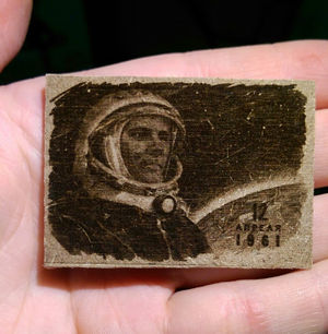
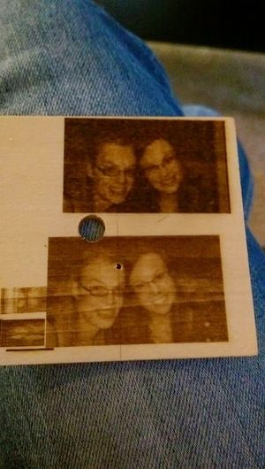
Solidoodle 3 2W Blue Laser Results
Etching paper has proved pointless, as the difference between a mark and a full through burn is incredibly small. However, balsa wood has proven to work extremely well and the results have been most satisfying!


