Difference between revisions of "Yaris Remote Start"
(Restoring from arhives, still need to red hilight) |
(Added photo of finished unit) |
||
| Line 1: | Line 1: | ||
==Problem Statement == | ==Problem Statement == | ||
My 2007 Yaris doesn't have remote start or door lock / unlock capabilities. In Arizona its REALLY hot in the summer and even hotter inside a car-oven. Easily 170 degrees on a dash. I would like to design a system to interface with my EZ430 Chronos wrist watch as well as my home wireless network (CC2500 based) that is capable of remote starting the car in order to cool it down. Temperature information can be relayed by the MSP430 chip which will be inside the dash or by a secondary wireless node that is directly exposed to the interior temperature. | My 2007 Yaris doesn't have remote start or door lock / unlock capabilities. In Arizona its REALLY hot in the summer and even hotter inside a car-oven. Easily 170 degrees on a dash. I would like to design a system to interface with my EZ430 Chronos wrist watch as well as my home wireless network (CC2500 based) that is capable of remote starting the car in order to cool it down. Temperature information can be relayed by the MSP430 chip which will be inside the dash or by a secondary wireless node that is directly exposed to the interior temperature. | ||
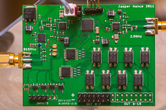
| − | + | <flickr>8436023972|m|none|thumb|Populated Board</flickr> | |
==RF Interface == | ==RF Interface == | ||
Revision as of 09:53, 1 February 2013
Problem Statement
My 2007 Yaris doesn't have remote start or door lock / unlock capabilities. In Arizona its REALLY hot in the summer and even hotter inside a car-oven. Easily 170 degrees on a dash. I would like to design a system to interface with my EZ430 Chronos wrist watch as well as my home wireless network (CC2500 based) that is capable of remote starting the car in order to cool it down. Temperature information can be relayed by the MSP430 chip which will be inside the dash or by a secondary wireless node that is directly exposed to the interior temperature.
RF Interface
The design will have two radios.
A 915Mhz CC1101+CC1190 radio with 500mW TX power and a 6dB LNA. This will interface with the EZ430 Chronos wrist watch and other CC1101 designs including a possible high-power key-fob so that you can be cool all the way from your office. A CC2500 2.5Ghz 3mW in-car network for transfering data to and from expansion nodes. This will work with EZ430-RF2500 boards and other CC2500 based designs include things like hidden GPS nodes.
Yaris Inputs and Outputs Required
The outputs will be provided by clocking the data words into a latching shift register which will drive opto-isolators. This will provide maximum circuit flexibility in case of polarity confusions or unknowns while also keeping the car safe from short circuits or board mistakes (because my Yaris is more expensive than this circuit).
Board Outputs
15 opto-isolated (FOD852SD high gain 150mA, 150mW optocoupler) channels, not all of them used
- Door lock
- Current draw: ~20µA
- Low pulse locks all doors
- Door unlock (pull low)
- Current draw: ~20µA
- 1rst low pulse unlocks driver door
- 2nd low pulse unlocks all doors
- Accesory Wire (full 30A from AM1!! External relay required!!)
- Not needed for remote start anyway unless you want the radio to blare when you aren't in your car.
- 15A Cig (behind cut-off during start relay)
- 7.5A ACC (behind cut-off during start relay)
- 7.5A ACC2 (shift lock, only on A/T)
- Ignition 1 Relay Wire
- Current draw: (not yet measured)
- Pull to +12V (AM1) to enable the following circuits
- 10A ECU-IG signal
- 25A WIP (front wiper and washer)
- 15A WSH (front wiper and washer)
- 10A Gauge
- 15A RR WIP (rear wipers)
- 7.5A A/C (Air conditioner and rear window defogging)
- Ignition 2 Relay Wire
- Current draw: (not yet measured)
- Pull to +12V (AM2) to enable the following circuits
- 7.5A IGN (signal to ECU, looks like it controls fuel injectors)
- 7.5A MET (battery charging and running light control)
- ST2 starter relay wire
- Current draw: Variable.
- 380mA if IG1/IG2 are not pulled high already (probably bad).
- 12mA steady until the clutch switch is closed.
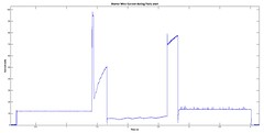
- Closing the clutch switch results the following waveform with a ~40ms duration peak at ~100mA and a smaller longer climb to 80mA following cranking.
- Pull to +12V (AM2) to enable the following circuits
- ECU Starter Pin (not sure what this does but I assume its important that the ECU know when the engine is attempting to start)
- Direct battery link through engine starter
- Dependant on Clutch Sw for M/T
- Clutch switch bypass (not needed for A/T)
- Current draw: (not yet measured)
- In series with Starter relay.
- Can intercept post-sw and pull to 12V or
- Can bring both sides to opto and bypass
- Parking Light Relay (Hatchback only, D4, pin 13, white)
- Current draw: (not yet measured)
- Low pulse activates relay for duration of pulse
- Sedan pulls current directly through the light switch, 10A max. External relay required!
- Hazard Sw Relay (J/B 4S, pin 17, black)
- Current draw: (not yet measured)
- Low pulse activates relay for duration of pulse
- Horn Relay
- Current draw: (not yet measured)
- Low pulse activates relay for duration of pulse
Board Inputs
5 Logic channels (12V tolerant, translated to MSP430 operating voltage)
- Parking Brake sense wire to avoid starting in gear?
- Brake sense wire so that the car knows you are now in control (and drop all relay lines)
- Door lock (low pulse, so that the board is aware of the state of the car)
- Door unlock (low pulse, so that the board is aware of the state of the car)
- Future Hood Switch to kill the car of the hood is opened?
1 ADC channel
- Battery Wire (+12V) for Vbatt sensing
PC Board
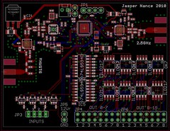
A PC Board will be fabricated which will contain a single MSP430f2274 chip and two radios - a CC1101 + CC1190 PA/LNA and a CC2500 radio for future in-car projects. The following is a screenshot of the board which will measure 7.2 cm x 5.4cm
BOM
Bill of Materials in XLS Format
Development Chronology
Nov 27th, 2010. Board design started. Used the CC1101 to CC2500 repeater as a template.
Dec 5th, 2010. Board design finished. Jacob Rosenthal showed me seeed studio's PCB service which offers 6 mil traces and 12 mil drills. 10cm x 10cm max, 10 boards for $40. Can even get them in pretty colors for +$10. He also convinced me to make it open source and universal. Hopefully this design will work with any make/model car or truck.
Dec 7th, 2010. Some updates, found a smaller package for the 74594 and redesigned the RF microstrips for a 31 mil board instead of a 63 mil board. Added a 5th input channel.
Dec 12th, 2010. Hotwired the car for the first time and measured the relay currents. Some are larger than expected, I need to see if the relays will still activate with inline resistors and what the dropout current is. Used posi-taps and T-taps and feel that the t-taps are better for large wires and posi-taps better for small wires.
Dec 21th, 2010. Attempted to hotwire the car using the ILD217T optocouplers. The optocouplers CTR ratio is terrible at the current level required to activate the relays on the car and the units overheated before actually driving them. A new optocoupler must be sought...
Jan 4th, 2011. Recieved the new optocouplers, FOD852. At 1.5mA drive the output was able to activate all relays on the car including the starter line (which has the odd profile). The opto is in a larger single package... but at least it will work! Now to fit 16 of them onto the board...
Jan 12th, 2011. Sadly, these new optos are so large that I can only fit 8 of them onto one side so the other 8 had to go on the back. But the layout changes are complete. Last step is to decouple the CC1190 because I think I forgot to do that. Then its off to the fab!
Jan 27th, 2011. Decoupling caps and inductors added to CC1190. Off to the fab after the Chinese Spring Festival is over on the 10th of Feb.
Mar 12th, 2011. Boards are in from the fab!
Mar 13th, 2011. Population of boards about 50% complete pending a digikey order.
Apr 7th, 2011. Digikey/Mouser order filled. Can't wait to get this thing done!
Apr 25th, 2011. Board populated. Shift registers and PA inductors on backorder following the disaster in Japan.
May 1st, 2011. Basic software written, acting only as a radio bridge (CC1101 repeats to CC250 and vice versa). Problem found with crystal capacitor loading. 32-mil boards display 26.0009Mhz (10pF probe load) while Chronos watch displays 25.9990Mhz (10pF probe loading). Need to increase crystal loading from 15pF to possibly 20pF.
June 15th, 2011. Crystal loading found to be right on at 24pF :)
July 9th, 2011. Populated shift registers and wrote a quick test code. Looks like its working wonderfully. A quick reflow of some nasty solder joints resulted in a VCC to Ground short. Reflow damaged a 100nF filter cap on the CC2500 which took several days to fix. Last steps are to write the shift code and populate PA
Jan 22, 2013. Discovered a crakced inductor that was blocking the 915mhz output. Took the time to populate the RF PA/LNA. Totally worked!!
Source Code
MSP430 code be found here (For reference only, all rights reserved) Users are encouraged to 'hack it all up' not only because its fun to do but for the security of the automobile!
Disclaimer
Don't whine to me if you brick your car, its not my fault. PLEASE do your own backup research especially if you don't own a 2007 M/T Yaris! DO NOT IMPLICITLY TRUST ANYTHING ON THIS PAGE! You have been warned!
2013 Jasper Nance KE7PHI


